
Three Foot Flag Assembly Installation Instructions
The following installation instructions are for bicycles that have a rear rim or hub brake.
For most bikes with rear disc brakes, please see the separate install modifications instructions.
The following installation instructions are for bicycles that have a rear rim or hub brake.
For most bikes with rear disc brakes, please see the separate install modifications instructions.
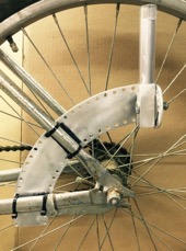
Figure A is the finished installation on a common bike frame. There are many bike frame configurations depending on the manufacturer and models, therefore your installation may look slightly different. Try to configure your installation so that the assembly is positioned similarly as the one in Figure A. The adjustable mechanism must be in a vertical position. Also, it is preferable that the adjustable mechanism be above and somewhat behind the rear axle as depicted in Figure A.
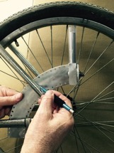
Figure B shows hand positioning the flat mounting surface and placing pencil marks on the mounting surface identifying where it will attach to the frame members. The holes used for the four nylon straps should be as close to the edge of the frame member as possible with the strap head tucking below the frame member when tightened and not protruding out to the side from the frame member. In the case of a round frame member, the holes used should be slightly tucked under the edge of the frame member without interfering with the contact between the assembly flat mounting surface and the bike frame members. Make sure the position of the mounting plate does not interfere with the removal of the rear wheel.
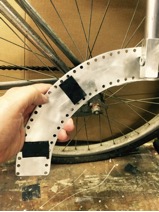
Figure C shows placing two provided mastic strips pressed on between the pencil lines drawn in step 1. The use and correct positioning of the two mastic strips is critical to the long term success of the installation. The mastic strips are made of a unique material that contributes to the rigidity of the assembly as well as protecting the frame’s finish.
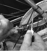
A very good technique to use when tightening the nylon straps is to use a flat head screwdriver in conjunctions with a pair of pliers as depicted in Figure D. The straps should be pulled very tight so that the faint clicks of the nylon head being tightened are no longer heard and there is no excess slack of the nylon straps on the backside of the mounting plate. Once tightened, cut of the strap tails close to the heads.
The SafetyFlag assembly allows the bike rider to quickly adjust the safety orange flag to one of five optional positions depending on riding conditions. Each position offers different effective horizontal indications from zero inches to thirty-six inches.
To utilize the SafetyFlag mechanism, the fiberglass rod must be fully inserted into the adjustable mechanism so that the aluminum collar affixed on the fiberglass rod comes in contact with the aluminum tube of the adjustable mechanism. The fiberglass rod is designed to pull out of the adjustable mechanism if the rod or flag becomes entangled with anything that could disrupt the bike and its rider. The rider can choose to separate the rod and flag from the bike if it is preferred not to leave it with a parked bike.